Gates, Laziness, and Automation
· 5 minThe following is an overview of how I built and installed an automatic vehicle entry system at my dad’s house using an IP camera and a Raspberry Pi. The camera at the front gate reads the license plate as the car approaches, and triggers a relay to open the gate if it recognises the vehicle.
But before we get into the details, a demo!
Equipment I used
- A PoE camera that has motion detection capabilities. I chose this model.
- A spare remote for your gate.
- Raspberry Pi or Arduino.
- 5v relay. I went with this fella because it was cheap and I could get it locally.
- An ethernet cable long enough to reach from the camera to a network switch.
- Conduit housing for the ethernet cable.
- A few jumper and plain wires.
Technical Details
The first order of business was setting up the Pi. I decided to use Balena to help with this. Balena allows me to easily push code to the Pi remotely, monitor logs and health via the cloud, and ease the flashing/setup process which is typically a headache.
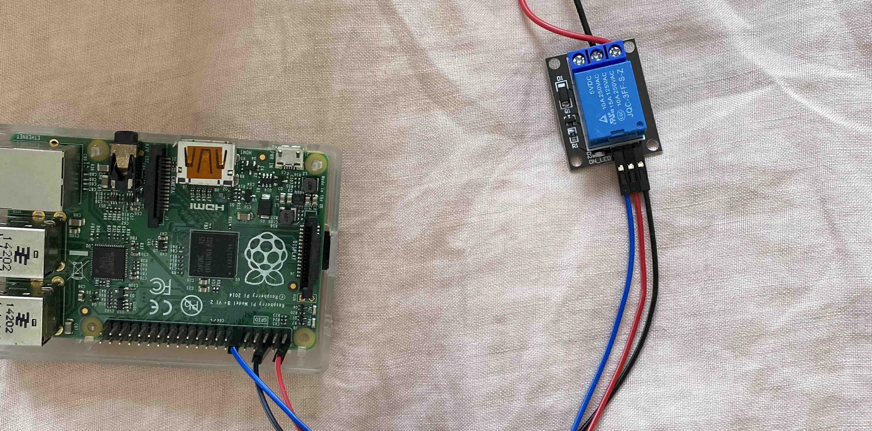
After I got the Pi setup, and validated that I could push code to it and execute that code, I decided to test the relay. In order to get the relay connected to the Pi, I attached jumper wires from the VCC, GND and IN pins of the relay into the GPIO pins of the Pi (specified by the relay's documentation).
I then wrote some code to turn on and off the relay to make sure I wired everything correctly.
After validating that the Pi can trigger the relay, I wired up the outputs to the remote control. In case you’re wondering, it’s also possible to avoid all of this wiring by relaying the RF signal from the Pi using a RF module. However, most modern gates/garage doors protect against this which makes it a little more difficult.
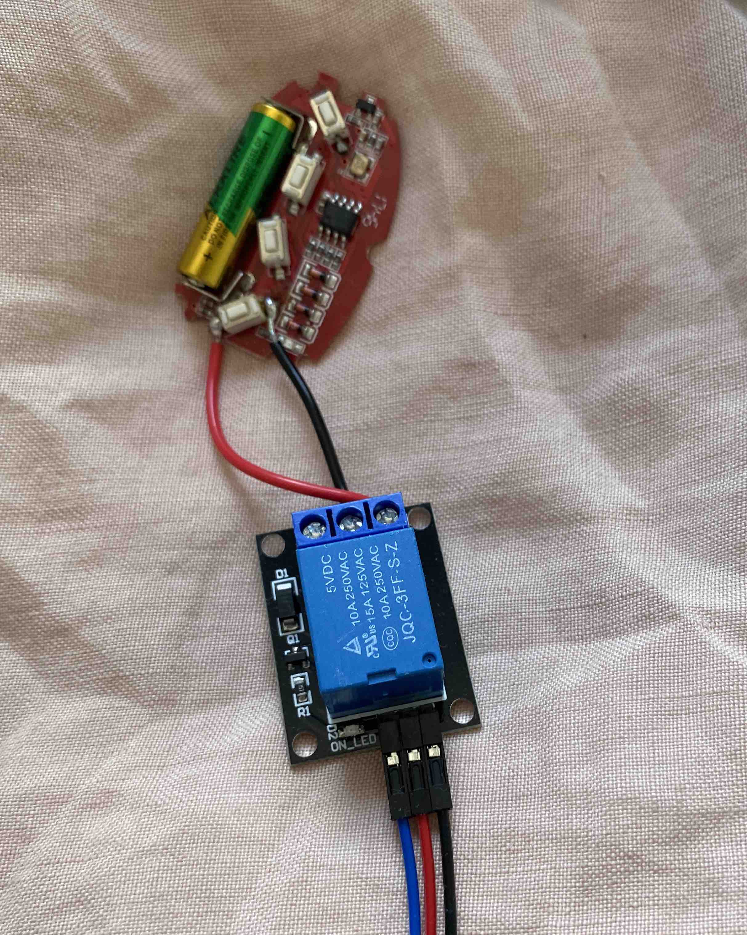
As you can see, I've soldered the wires from the relay's NC and C terminals to the two terminals of the remote button (make sure it's the right button.. I wasted a few hours because of this). Essentially, it's just shorting the circuit to trigger the remote. Quick side note, it's also possible to connect the relay to the gate directly, however, not feeling like getting electrocuted or bricking the gate I opted for the simpler solution of wiring into the remote directly. Another option is to use an optocoupler instead of a relay but again, I decided to go with the simplest solution for this experiment.
Now for the camera. Unfortunately, the model I purchased was getting a little long in the tooth and as a consequence, only allowed me to send frames on motion over FTP. I wrote a simple FTP server to run on the Pi and process the frames as they come in. When a new frame hits the server, it sends it over to PlateRecognizer, a great service to find any license plates that could be in the frame. If we find a plate that is in our whitelist (defined in a config file), we simply trigger the relay to open the gate. There's obviously a little more to it than that, such as finding the “best” frame out of a batch, so I urge you to take a look at the code if you're following along.
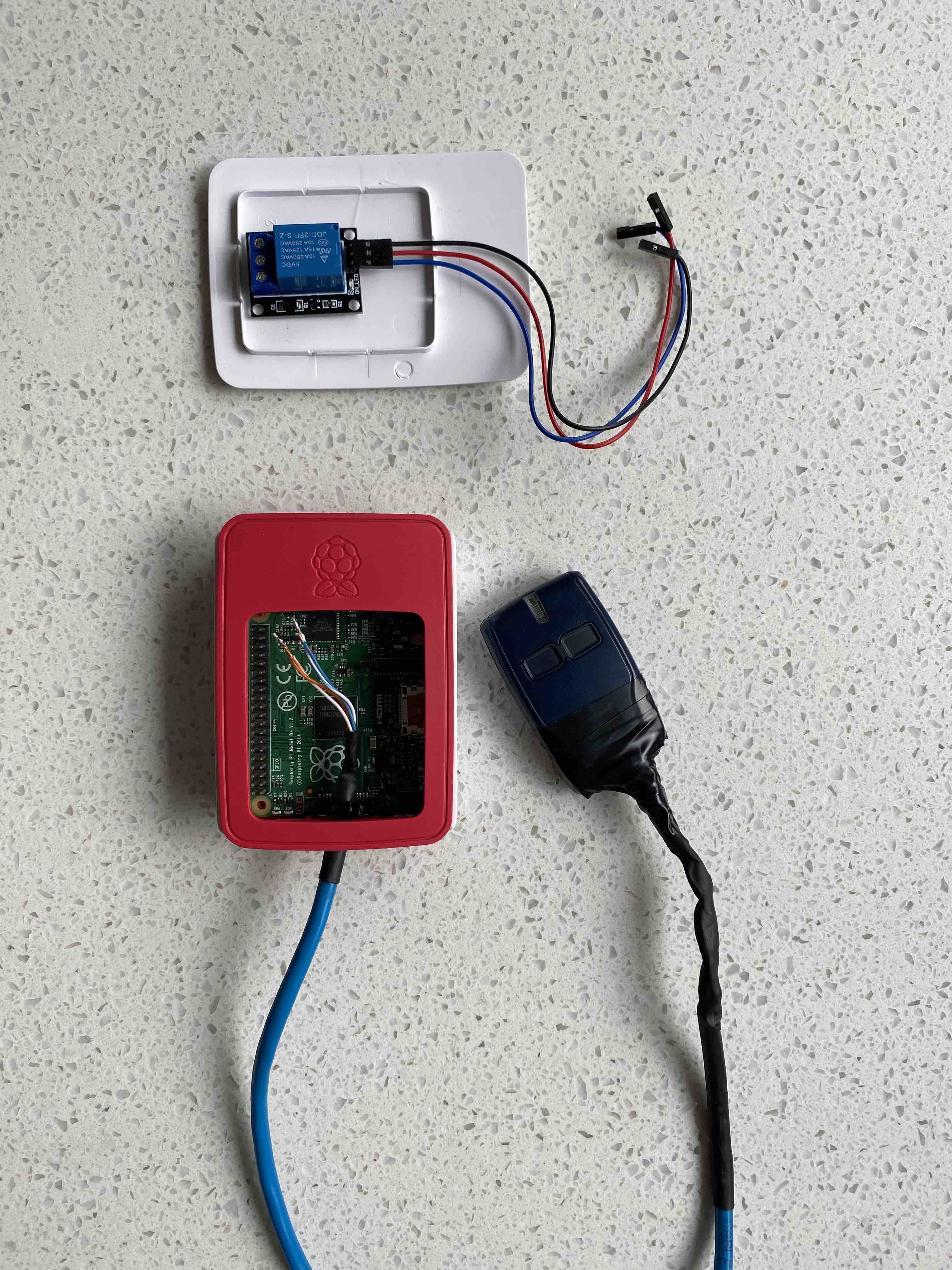
We've now got a Pi that can receive frames from a camera, check for license plates, and open a gate if it sees someone it recognises. I decided to do a little house keeping and put the Pi in a case, as you can see below.
Installation
The distance from the front gate to the PoE injector inside the house is roughly 35 meters, which is a little too far for stray cable. We decided to dig a shallow trench from the house to the gate and run the ethernet cable underground in some conduit housing. Funnily enough, this turned out to be the most difficult and time consuming part of the whole process.
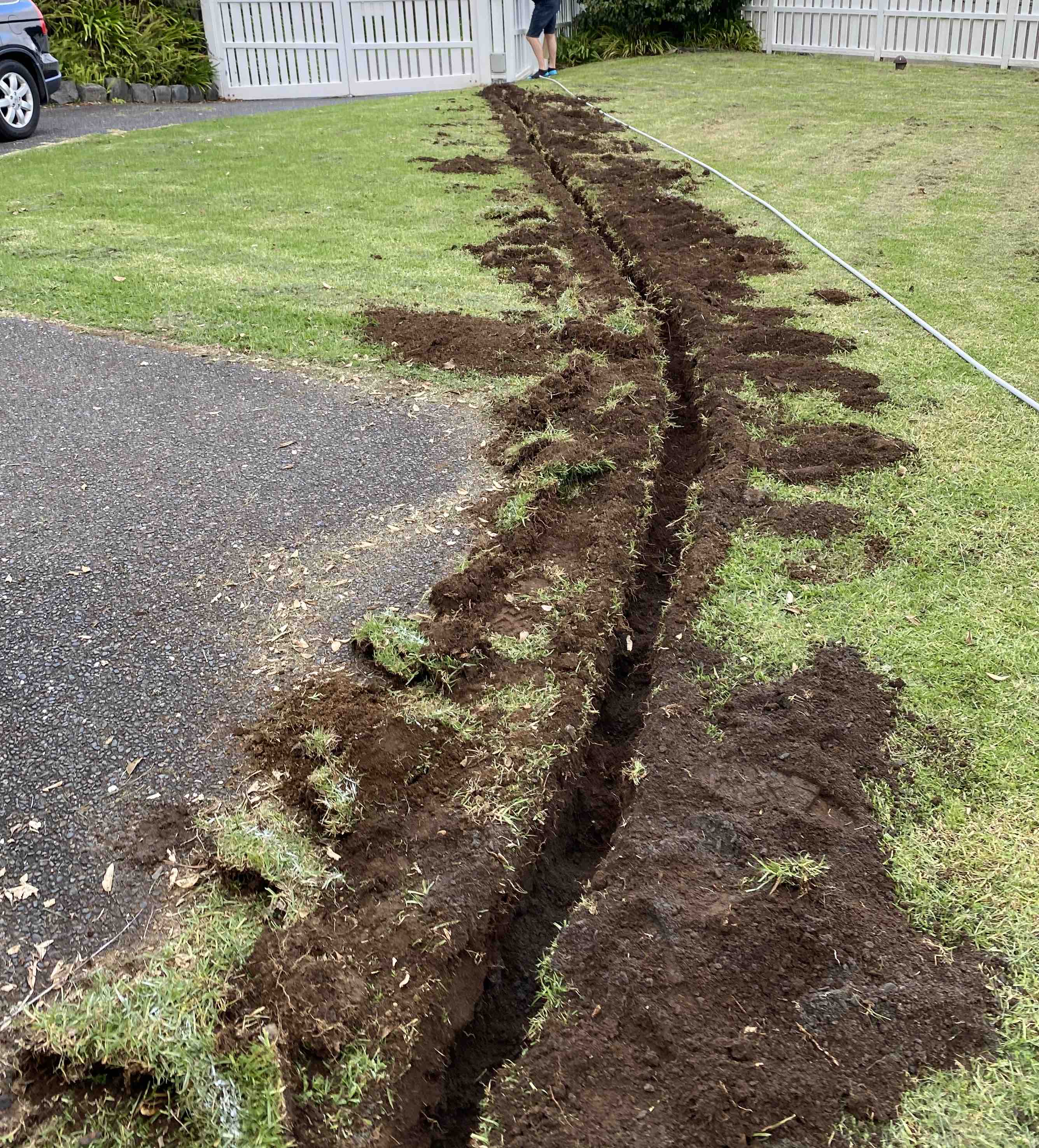
That's about it. Slapped the dirt back on, appologized for the hole in the yard, and began testing. Here's what the camera looks like from the outside.
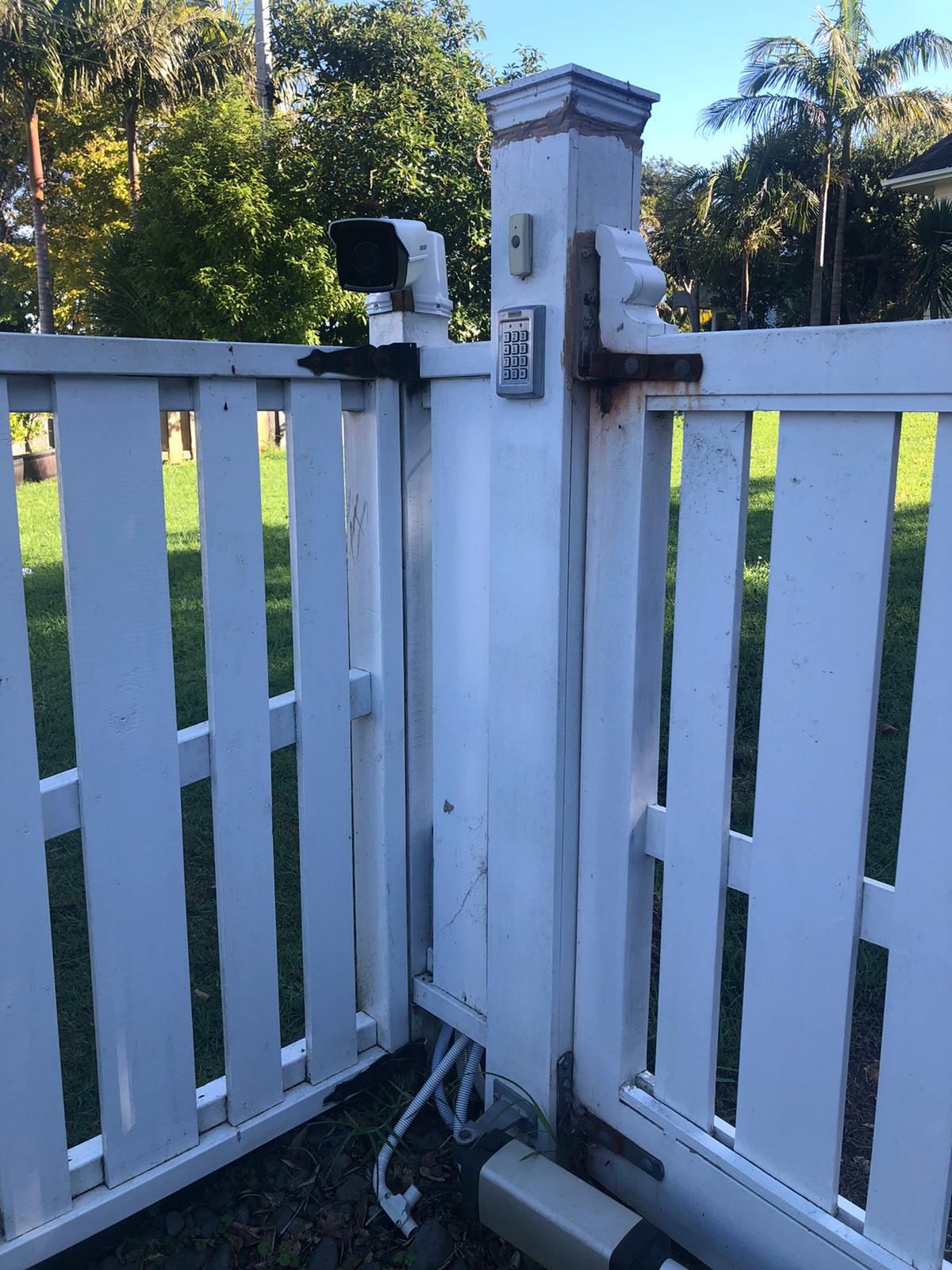
And yup.. that's a bucket covering a small exposed gap in the mount that covers the wiring.
I'm planning on building a simple mobile app shortly that will be able to receive push notifications of unknown vehicles at the gate, trigger the relay manually, and more.
I hope you enjoyed the post. If you're looking for a bit more detail or have any questions about how this system was built, reach out via email (it can be found in my CV on the home page). This was a super fun project to work on with and for my dad, and hopefully I will be able to post more projects like this one in the near future.
